Er Satish Barmade/ July 25, 2020/ Er Satish Barmade, Geoenvirovision, Pavement Engineering/ 1 comments
Highway pavement is a structure that provides users durable surface for quality riding experience. In engineered terms highways pavement is a structure of superimposed layers of processed materials above the natural stratum (sub-grade). The structure is basically designed to distribute the applied vehicle loads to the sub-grade. The pavement structure should have a surface that provide the acceptable riding quality, adequate skid resistance. Further, the pavement material should be selected so as to provide a light reflection and also low noise pollution. Although, pavement must have to serve for its basic purpose of transmission of stresses induced due to the wheel load. The quality pavement should be frequently evaluated.
Pavement evaluation is of two types
- Structural evaluation
- Functional evaluation
Structural Evaluation of flexible pavement at various location helps to evaluate whether the pavement is structurally capable for design traffic, and climatic condition. Structural adequacy is the primary response of pavement to transient loads and consists in deformation, deflection, stresses, strain and permanent deformation at critical points in pavement layers. Generally, for structural evaluation deflection criteria are widely used.
Following is the explanation of deflection measurement using Benkelman beam deflection method.
Deflection study using Benkelman Beam Test
The Structural evaluation of flexible pavement by Benkelman beam deflection (BBD) test is based on principal of surface deformation under an applied wheel load, this depends on,
- Sub-grade soil, moisture content its compaction,
- Thickness and quality of various layers
- Drainage condition
- Pavement surface temperature
Description of Benkelman Beam Equipment and Procedure
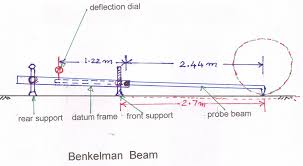
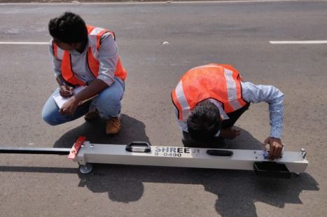
The Benkelman Beam shown in Fig. 1. Benkelman beam has a movable beam attached through a fulcrum to a fixed base which rests on the pavement surface. The beam apparatus is placed on the road surface with the extreme end or tip of the beam resting and remaining on the pavement surface at the point where the deflection is to be measured. Movement of the tip of the beam is measured by a dial gauge, which is in contact with the other end of the beam.

Benkelman Beam Deflection
The Benkelman Beam deflections should be measured at 20 points in each kilometre, staggered at 50 m interval in both directions with truck having rear axle load of 8.17 tones and Tyre pressure of 5.6 kg/cm2. The measurements should be made in accordance CGRA procedure laid down in IRC: 81-1997.
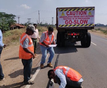
The truck should be driven slowly parallel to the edge of road and stopped such that the left side of the rear dual wheel placed centrally over the point of deflection measurement. The probe end of the Benkelman beam inserted between the gaps of the dual wheel and is placed exactly over the deflection observation point. When the dial gauge reading is stationary note the initial dial gauge reading as D0. The truck moved forward slowly through a distance of 2.7 m from the initial point and stopped. The intermediate dial gauge reading noted as Di. Typically, intermediate reading noted when the rate of recovery of the pavement is less than 0.025 mm per minute. The truck is then further driven forward through a distance of 9.0 m and the final dial gauge reading Df is recorded. The three deflection dial readings D0, Di, and Df forms a set of readings at one deflection point under consideration. Similarly, the truck is moved to the next deflection point and the procedure is repeated. The temperature of the pavement surface should also be recorded at intervals of an hour during the observations. The moisture content of the sub grade soil is also to be determined at suitable intervals, the rebound deflection value D at any point is given by one of the following two conditions
- If Di – Df ≤ 2.5 divisions of the dial gauge or 0.025 mm, D = 2 (D0 – Df) divisions of 0.01 mm units = 0.02 (D0 – Df) mm
- If Di – Df ≥ 2.5 divisions of the dial gauge or 0.025 mm, this indicates that correction is needed for the vertical movement of the front legs.
Correction applied is
D = 2 (D0 – Df) + 2 K (Di – Df) divisions.
Then Temperature and sub-grade moisture correction should be applied.
| Strength of Pavement | Rebound Deflection |
| Strong | Upto 1 |
| Moderate | 1 to 2 |
| Weak | 2 to 3 |
| Very Weak | >3 |


Great work done sir